SPECIFICATIONS
Furnish ______ Rockford Model GF-______ all-welded steel separators with integral extension of ______ ” to grade, ______ g.p.m. intermittent flow, ______” tapped inlet and outlet with outlet vent connection, 2″ tapped internal rear vent connection, ______lb. greasy sludge capacity, visible double-wall outside trap seal, non-removable separator screen and easily removable filter screen, removable 3/8″ nonskid diamond treadplate cover for flush-with-floor installation suitable for pedestrian traffic and secured with stainless steel flat head screws, OPEX® Shop Coat coating inside, bituminous coating outside. Specify R (right hand) or L (left hand).
OPTIONAL FEATURES
6” Bolt On Extensions Available!
Our Stainless Steel units offer users a simple and economical solution to add an extension to units that are buried below ground. Our extension units are pre-fabricated in standard 6” increments so there’s no measuring or cutting required for installation. Because of the inherent strength of steel, our extension units are much more reliable at ground level, which is the primary location where damage can occur. The design also gives you 100% accessibility for cleaning and maintenance.
CONSTRUCTION
A compact, one-piece separator with integral extension built to exact requirements. The built-in strength of solid walls eliminates leaks caused by vibration and traffic in bolt-on extensions.
Constructed of all-welded heavy gauge steel with corrosion-resistant coating, the separator features a removable nonskid flush-with-floor cover of heavy steel plate with leakproof and airtight gaskets, secured to the body of the unit with recessed stainless steel bolts, a separator screen and removable flow-regulator filter screen, a standard tapped inlet and outlet, and protective seal outlet. Concrete reinforcing anchor rings are optional.
Choice of outlet location saves space, labor, pipe and fittings. Outlet tee can be turned up to 90 degrees in either direction. Depth of inlet and outlet varies.
HOW TO ORDER
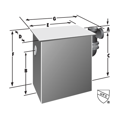
When an extension is needed to meet roughing-in on a flush-with-floor installation, select the separator of the right size and capacity. Then determine the required dimension A from the center of the outlet to the top of cover, and order accordingly. Dimension A is variable and can be specified to a fraction of an inch. The inlet opening is lower than the outlet opening to assure a wet inlet at all times. All separators with extensions have flush-with-floor covers.
NOTE
NOTE
Specify M (Outlet opposite Inlet), L (Left Hand Outlet), or R (Right Hand Outlet) on your order.
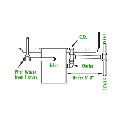
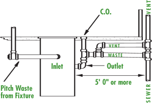
TYPICAL INSTALLATIONS OF SEPARATORS SET FLUSH-WITH-FLOOR
† Anchor flange requires 3″ extension.
* Also available with 2″ inlet and outlet.
+ Internal vent connection is located on outlet wall, right-hand side of the outlet.
| Model | Intermittent Flow GPM | Tapped Inlet and Outlet (in.) | Static Holding Capacity (gal.) | Greasy Sludge Capacity (lb.) | Top to Center of Outlet A (in.) | Bottom to Center of Inlet B (in.) | Bottom to Center of Outlet C (in.) | Width D (in.) | Length E (in.) | Height F (in.) | Overall Length G (in.) | Tapped Internal Vent + (in.) | Bottom to Rear Vent + (in.) | Shipping Weight (lb.) | PDF Specification Drawing | CAD Specification Drawing |
|---|---|---|---|---|---|---|---|---|---|---|---|---|---|---|---|---|
| GF-1412 | 12 | 2 | 5.3 | 27 | 2.25 | 8.38 | 10.75 | 13v | 15.5 | 13 | 19.25 | - | - | 77 | L M R | L M R |
| GF-1815 | 16 | 2 | 10 | 50 | 2.5 | 11 | 13.25 | 13v | 21.25 | 16.25 | 26 | - | - | 108 | L M R | L M R |
| GF-1820 | 20 | 2 | 17 | 86 | 2.5 | 12 | 15 | 17 | 23 | 17.5 | 28.75 | - | - | 132 | L M R | L M R |
| GF-2420 | 30 | 3 | 31 | 156 | 3.13 | 14.5 | 17.88 | 21 | 27.25 | 21 | 34 | - | - | 203 | L M R | L M R |
| GF-2635† | 35 | 3* | 40 | 202 | 6 | 16.5 | 21 | 21 | 27.25 | 27 | 34 | 2 | 23.75 | 252 | L M R | L M R |
| GF-2824† | 40 | 4 | 54 | 272 | 5.25 | 21.5 | 25.75 | 23 | 29 | 31 | 37.75 | 2 | 27 | 304 | L M R | L M R |
| GF-3050† | 50 | 4 | 60 | 302 | 5.25 | 21.5 | 25.75 | 23 | 32.25 | 31 | 41 | 2 | 27 | 330 | L M R | L M R |
| GF-3224† | 60 | 4 | 67 | 338 | 5.25 | 21.5 | 25.75 | 23 | 35.75 | 31 | 43 | 2 | 27 | 377 | L M R | L M R |
| GF-3475† | 75 | 4 | 80 | 403 | 4.75 | 22 | 26.25 | 25.5v | 35.75 | 31 | 44.38 | 2 | 27 | 398 | L M R | L M R |
| GF-3628† | 100 | 4 | 110 | 554 | 4.75 | 22 | 26.25 | 32.75 | 38.25 | 31 | 46.63 | 2 | 27 | 507 | L M R | L M R |
| GF-23-LO | 16 | 2 | 10 | 50 | 1.25 | 6 | 8.75 | 17 | 23 | 10.63 | 28.75 | - | - | 111 | L M R | L M R |
| GF-25-LO | 20 | 2 | 21 | 106 | 3 | 6.5 | 10.25 | 23 | 29 | 13.25 | 33.75 | - | - | 186 | L M R | L M R |
| GF-30-LO | 30 | 3* | 23 | 116 | 3 | 6.5 | 10.25 | 23 | 33 | 13.25 | 39.75 | - | - | 195 | L M R | L M R |
| GF-36-LO | 35 | 3* | 28 | 141 | 3 | 6.5 | 10.25 | 23 | 39 | 13.25 | 42.75 | - | - | 257 | L M R | L M R |
| GF-45-LO† | 40 | 3* | 37 | 186 | 5 | 6.75 | 11 | 23 | 47.25 | 16 | 54 | 2 | 12.5 | 325 | L M R | L M R |
| GF-50-LO† | 50 | 3* | 41 | 207 | 5 | 6.75 | 11 | 23 | 52.25 | 16 | 59 | 2 | 12.5 | 341 | L M R | L M R |


